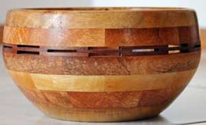
Part 1 discussed designing a segmented bowl using graph paper and some Maths.
In Part 2 I’ll show the same bowl designed using a software program.
There are a few popular programs to aid in segmented designing but I’ll just be going through the one I use called ‘Segmented Project Planner’. See Segmented Turning
Below is a sample of the screen for this software.
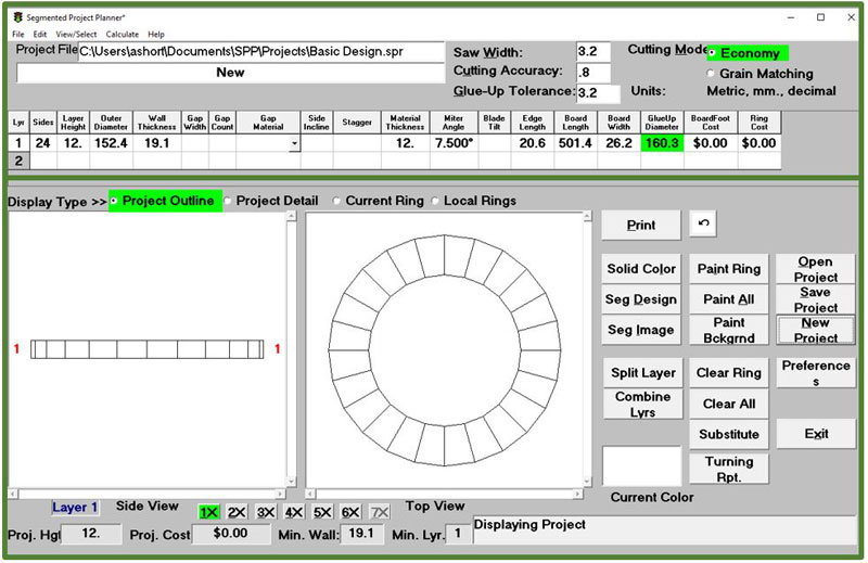
You can download the trial version of this software from the web site or purchase for $US36.95

Once the software is installed, the first step is to set your Preference which you can find under the Edit menu.
From here you can set up criteria such as:
- Max swing is the lathe
- Default wall thickness
- Default number of segments per layer
- Saw blade kerf
- Cutting mode of Economy or Grain Matching (see my Part 1 for an explanation)
- Setting units to Metric
- and many others

Now that the software is set up lets design the same bowl described in Part 1

There are some basic designs that you can pick to start and this bowl is one of them.
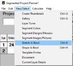
- From the View/Select menu select Sketch a Bowl
- From the bottom of the window, click on the arrow for the Select Base Figure and then select the Calabash.shp. This is the bowl we will work on.
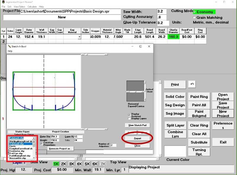
- Turn off the Constrain Proportions if you wish to duplicate my project
- Now change the Height to 132 mm and the Outer Dia to 200 mm. Ensure Sides and Layer Hg are set to 12.

- Click on Generate Project as… and save the project with an appropriate name
- Click on the Close button
Your window should look similar to this.
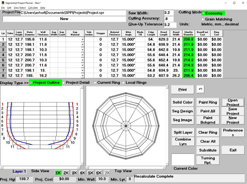
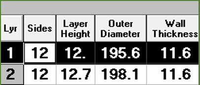
Because the software is designed for Imperial the Layer Height comes out at 12.7 m (1/2”) not 12 mm as we entered. See the Appendix 1 – Shortcuts on how to adjust the Layer information.
The red line represents the outside of the bowl and the blue the finished inside
Note the blue line is not very smooth.
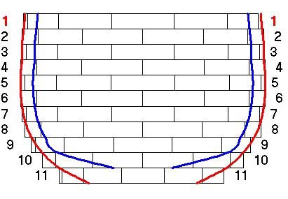
See Appendix 2 – How to adjust the Layers on how to change this.
So we have a design and now the benefit of using software comes home.
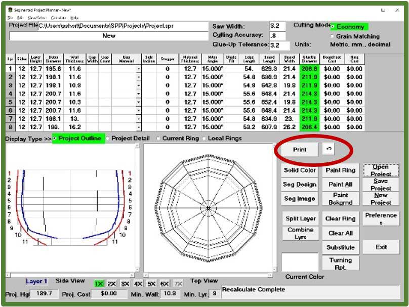
- Click on the Print button and select a printer. I usually print to a PDF file so it is saved for reference.
- Now you have a Print list to take to the shop.
BUT
- There is, however, a lot of information you probably won’t use so the format can be changed for what you need.

Here is how to change the format:
- From the File menu select Print then Format Project Report
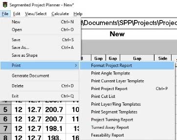
- Below is how I format the report by unchecking boxes and selecting some colors.
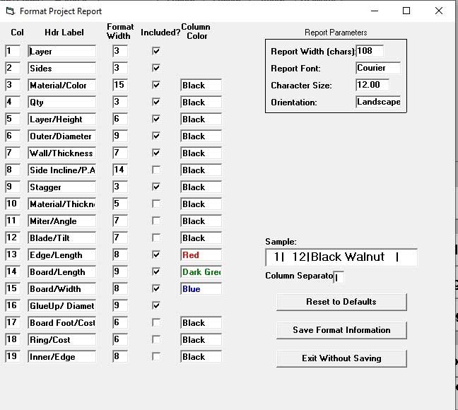
- I then save and reopen the project to ensure it has taken.
- The result provides all the useful information to take to the shop and make the project and the way I format the report applies color to the important figures for cutting.
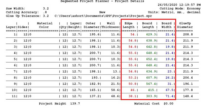
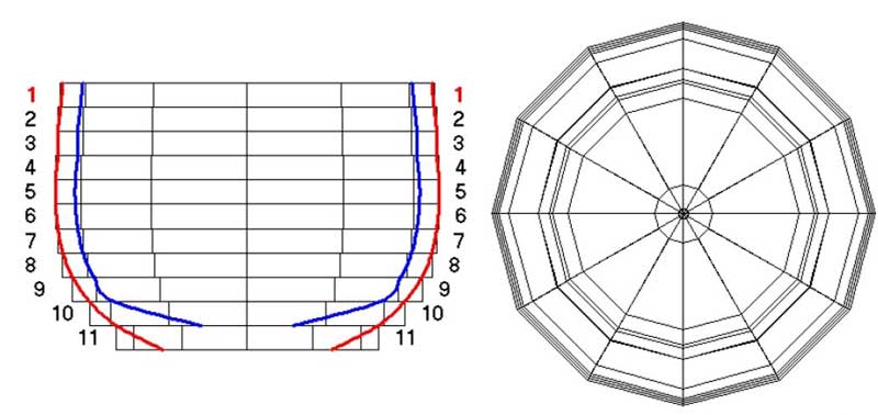
This output from the report shows all the joints lining up however when you construct the bowl you will stagger each layer in what is called the ‘brick layer’ pattern and we can show this by typing 50% into each of the Stagger fields in the table. The result is shown on the right.
More on the use of this is within Appendix 1 – Shortcuts on how to adjust the Layer information discussed below.
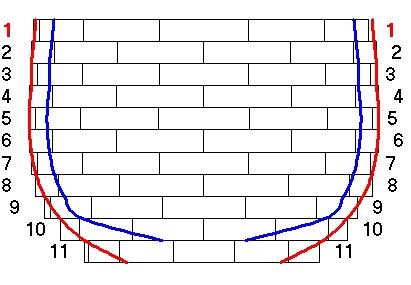
You are now ready to cut the timber and build your bowl. Remember a 12 segment layer is cut at 15 deg. See Some Basics in Designing a Segmented Bowl – Part 1 for more on this.
Additional information on using the software
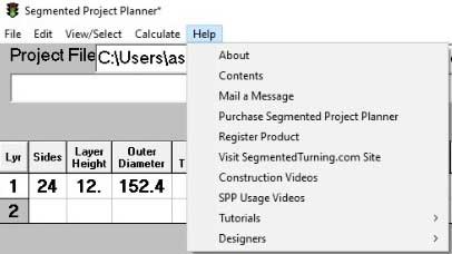
- The majority of the feature of the software are discussed in the SPP Usage Videos and Tutorials under the Help menu.
- There are a number of add-ons available for the software which incur a small fee to purchase their use. The one I use all the time is the Segmented Scene Designer which is accessible through the Edit and Designers menu.
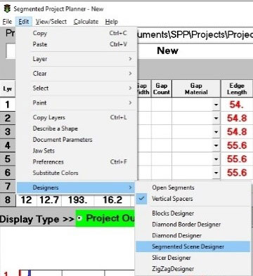
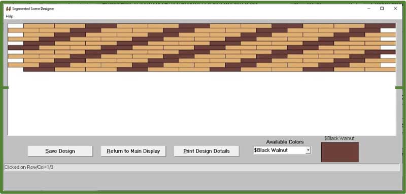
The Segmented Scene Designer provides a graphic matrix representing the layers and number of segments per layer as shown below for our bowl project
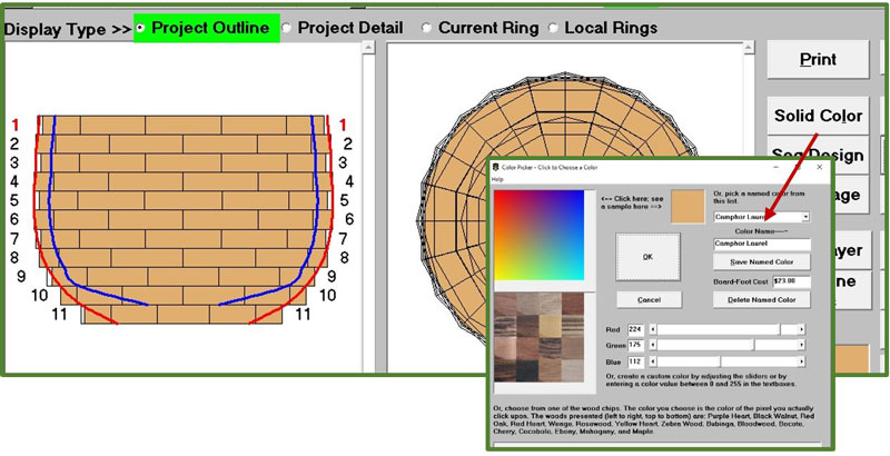
- First, however, I’ll select a timber type that makes up the majority of timber used by selecting the Solid Color button where there are pre-set timbers. You can add your our – I added Camphor Laurel so selected it then click on the Paint All button on the main display.
- Selecting the Segmented Scene Designer will show this display.
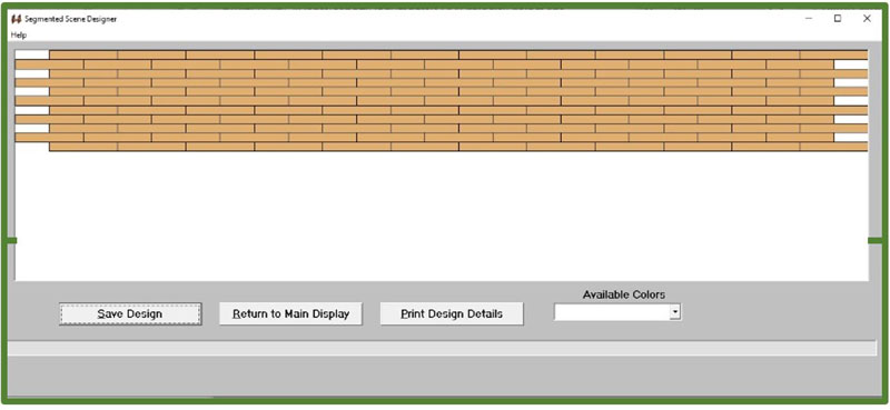
- Now click on the Available Colors and select, say, $Black Walnut
- Using your mouse while holding down the Ctrl key, click on various boxes to make a pattern. If you hit a wrong box, release the Ctrl key and click again to clear the box. Left click in a box will select that colour. Here is a possible pattern.
- Now click Save Design then Return to Main Display
- Returning to the Main Design will now show what the finished bowl will look like.
- Reprint the project will break down each layer by material type and number of each per layer – see below.
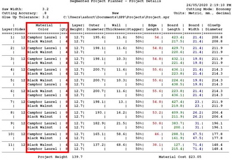
In Some Basics in Designing a Segmented Bowl – Part 1, I provided an explanation of working out the correct width to cut the board. This software does all that for you.
Assembling the Bowl
- Repeat the above for the other layers
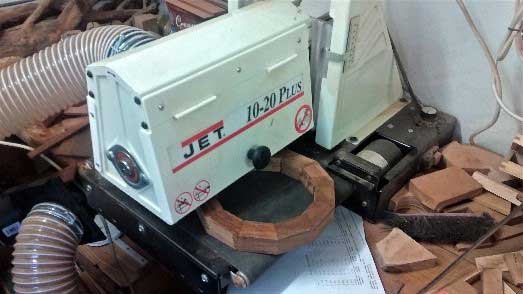
- Sand the layer flat. A disc sander or belt sander is great for this.
- I usually mount the bottom layer centered on a Faceplate with a piece of pine even if the bottom layer is a solid piece – no segments.
- After gluing a layer, I place it on the lathe and sand the surface using a piece of hardware board with 180 grit sandpaper. This ensures the layer is flat and ready for the next layer
The lathe speed I use for sanding is 800 rpm.
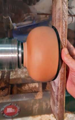
- After mounting about 3 or 4 layers turn the bowl to start developing the desired shape. The lathe speed for turning is about 1200 rpm.
Appendix 1 – Shortcuts on how to adjust the Layer information
As mentioned earlier, we entered a value of 12 mm for the layer height but the software changed that to 12.7 which is based on the software being developed for Imperial measurements.
This same process can be applied for adding a stagger to the layers.
You could over type the 12.7 with 12 into each of the fields in the table or do the following:
- In layer 1 click in the Layer Height field and type 12, then click outside the field but staying within layer 1.
- From the Edit menu select Copy Layers
- Click in the box next to Layer Height
- Then are 11 layers to the project but we have already changed one so only need to copy to 10 more. Enter 10 into the Copy This Many Layers (it still works if you do enter 11). Select Copy Selected Fields
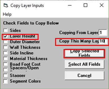
- You will note there are many other options available with this utility.
- Thus at anytime in the design you can quickly change multiple parts of your project.
Appendix 2 – How to adjust the Layers
We have designed a bowl, but the representation of the inner surface (blue line) is not smooth and therefore if we cut the timber as per the board width in the cut list we may not get the desired result.

This is where the Layer Turning Comes into use.
- From the View/Select menu select Layer Turner
- Through the use of the slides for Wall Thickness and Upper or Lower Diameter you can smooth the curve.
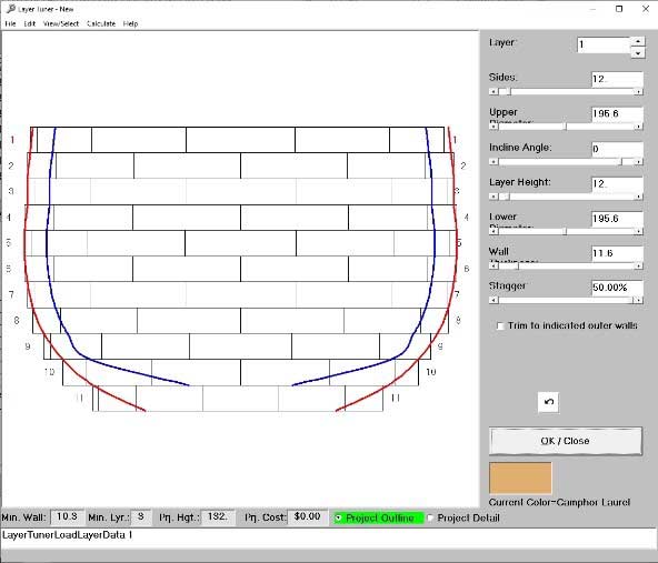
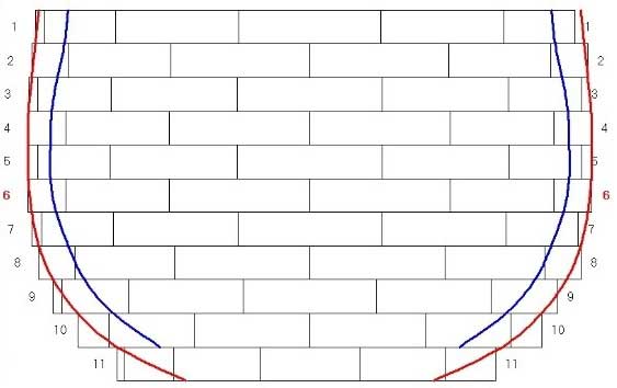
- I only needed to adjust the wall thickness for layer 10 and the lower diameter of layer 4 to achieve a smooth inside
- Mastering the Layer Turner does require practice as you often need to adjust the layer adjacent to the one you think is out to achieve the result.
Written by:
Allan Short
I can be contacted at:
ashort@carbatec.com.au or alswoodturning@gmail.com
See samples of my work at Als Woodturning Creations